Production


Window Sensor Wireless
Characteristics


 installation Procedure
- Magnetic pole invoice for tracking and transmitting information about the opening and closing of windows or doors.
- Power - internal Li-SOCL2 battery ER14250, 3.6V, 1200mAh
- Current consumption (open / close / transfer) - 4mkA / 4mkA / 140mA
- Service time without replacing the batteries - up to 10 years
- transmitting / receiving frequency of 2.4 GHz.
- Range indoors - 30 m.
- LED indicator - indicates data transfer and setup mode
- "Setting" button - to link the sensor to the control module
- Jumper Power
- User guide -

- Attach the sensor on the window, the frame magnet, the distance from the magnet to the mark on the sensor is not more than 5 mm
- Turn the power on by closing the jumper
- Transfer Control Unit in setting mode (putting a magnet on a label on the top edge, control - melody "There is a setting", orange light).
- Press and hold for 1-2 seconds on the sensor button "Installation" (on the control module sound "added Sensor"), release the button. After 2 seconds a double blinking - sensor is attached.
- Transfer control unit to the operating mode (removing the magnet from the top edge, control - tune "Getting Started" and the beeper on the number of connected sensors). The control module can support up to 10 sensors.
- The sensor works fully automatically after installation does not require intervention settings
- When changing the open-close there is a transfer to the control unit
- Sampling rate change condition - 4 seconds
- Periodically (1 time per 6 hours) transmitted information about the technical state of the sensor and battery voltage
Fan Coil control module
Characteristics
 installation Procedure
- Power - 220V
- Current Consumption 140mA
- Transmitting / receiving frequency of 2.4 GHz.
- Range indoors - 30 m.
- LED indicator - indicates operating mode, data transfer and setup mode
- Setting" button - Magnetic contact
- User guide -
- Structurally, the device is built into the wall
- Built part of the enclosure made in view of the wiring box diameter D = 65mm, H = 45mm depth.
- The front part is a plug socket outlet / switch size of 83mm x 83mm.
- With 220V terminals to provide power to the device.
- Other terminals are designed to break the chain of supply fan coil.
- For convenience, it is recommended to connect the module to install next to the fan coil embedded control.
- Transfer Control Unit in setting mode (putting a magnet on a label on the top edge, control - melody "There is a setting", orange light).
- Press and hold for 1-2 seconds on the sensor button "Installation" (on the control module sound "added Sensor"), release the button. After 2 seconds a double blinking - sensor is attached.
- If necessary, add more sensors
- Transfer control unit to the operating mode (removing the magnet from the top edge, control - tune "Getting Started" and the beeper on the number of connected sensors). The control module can support up to 10 sensors. (Repeat to add already installed sensor is permissible)
- The module operates fully automatically after installation does not require intervention settings
- The operating mode is displayed LED indicator: Green - ON, red - off, an orange - the installation
- When a state change signal goes open-close analysis of the situation, and if necessary, the fan coil switched on or off
- Turning off the fan coil to be after a delay (15 seconds), followed by the sound signals
- Turning the fan coil should be only after the closing of all windows
- Temporary, sound and logic module parameters can be adjusted via remote control devices and settings (optional), USB-interface, program
Remote control and adjustment, USB-interface, the program


- Interface - Mini USB
- Current Consumption 140mA
- transmitting / receiving frequency of 2.4 GHz
- Range indoors - 30 m.
- LED indicator - indicates operating mode, data transfer and setup mode
- Program for Windows
- Connect the device to your PC
- Standard Windows drivers will set their own
- After installing the drivers in the "Devices" added "HID nRF24L01P"
- Set FCDManager program
- Run the program, connect the device to the USB (control - in the status bar device is attached)
- Click "Add Device", fill in the address of the device (serial number on the label of the device type XX-XX-XX-XX-XX), the name and comments freely, save
- If necessary, add more devices
- Being in a radius of action of the device (making sure that it is turned on), click the "Query" button. The information displayed on the screen.
- The entire configuration is introduced, and the resulting data is stored and available for viewing outside the range of devices


The control module split - system

Purpose and Function
- The device is designed to reduce the electricity consumption of split systems by opening the windows and doors in the room
- The module monitors the power consumption and the presence of open windows (on the information received from the wireless sensors), correctly (via IR commands) off the air conditioner
- After closing the window unit correctly (using IR commands) includes a split system, if it has been switched off it
- The module is aimed at consumers - owners of office buildings and hotels (the space where people who are in them are not inclined to save energy)
Characteristics
- Power - 220V
- Current Consumption 140mA
- The transmission frequency / radio receiving at 2.4 GHz
- Transceiver - a transmitter in the infrared range
- Range indoors - 30 m
- Seven-segment indicator - indicates operating mode, supply voltage, load current consumption value
- Provided remote IR transmitter
Installation procedure
- Structurally the device is designed as a pass-through outlet D-character display
- The enclosure has the following dimensions: Height 50 mm; Width 57 mm; Length 124 mm
- The device is installed in the outlet for split-system was connected
- Plug the cord of split-system is connected to the device outlet
To set
- Insert the module into the socket - melody "start" and the indicator lights inscription "ACCx" (x-number of connected sensors)
- Press the button for 1-2 seconds "choice" and release - melody "installation" and the indicator lights inscription "CF-x" (x-number of connected sensors)
- To add a wireless sensor button to click on them - sounds sound "added" and the display module "CF-x" is increased by 1 if the sensor has not yet been attached
- For recording IR commands on-off split-system bring your console with the underside of the module and press on the remote control the air conditioner ON / OFF button with exposed operating parameters (temperature and operating mode) - the indicator lights "xxxG" (xxx-length command)
- In case if a split system ON and OFF commands are different (in these air conditioners is displayed on the remote is included or not), press on the remote ON / OFF button again to turn off the team record - the indicator lights "xxxL" (xxx- length of the command)
- To exit the installation, click "setting" - melody "start" and the indicator lights inscription "ACCx" (x-number of connected sensors)
- "ACCx" (x-number of connected sensors) under the regime of "on" (windows closed) or "----" in the off mode (a window is opened, air is switched off)
- "XxxU" - xxx - supply voltage
- "Xx.xA" - xx.x - current consumption
- "" - Without indication
Security alarm Signal-SM1

Budget solution for rooms with insecurity of food and light (wireless) installation and management of remote keys
Device capability
- Operation at power failure 7 days
- Supports up to 12 sensors:
- 10 wireless
- 2 wire
- status indication sensors, power supply, battery status
- sound signaling errors and modes of operation
- compatible device:
- wirelessly - sensor WS02
- on landlines - any sensor connected to the loops (NO- normally open, NC - normally closed)
- output for connecting NWD
- output for connecting a remote ICU
- control the availability of 220V
- arming and disarming via remote key fob (up to 4 units)
- setting the duration of the sound NWD
- setting the delay time to the input / output of the protected object
- restore factory settings
- Battery charge control
Characteristics
- transmitting / receiving frequency of 2.4 GHz
- Range indoors - 30 m
- Number of wireless unit: 10
- The number of wire units: 2
- Input voltage 100-240V
- Operating voltage 12V
- Current consumption in the mode of protection to 0.1A
- Current consumption maximum to 0.5A
- Power consumption 20-100 W
- Temperature range -20…+40°С
- Warranty service life of 12 months
- Weight 3.3kg
- Dimensions L x W x H mm 280 x 95 x 190
- User guide -
Equipment
- Alarm Signal-SM1
- Rechargeable battery 12V 7Ah
- Wireless sensors WS02 - 5 pcs
- Remote controls - 2 pcs
- remote LED
- Siren GNOM-1
- for mounting the siren 25m cable
- Translate alarm setting mode (to close the SETUP jumper control - orange and green indicators are flashing).
- Press and hold the sensor button "Installation" on it until indicator light flashes and goes out (2-3 seconds), the Control Unit red LED illuminates in the corresponding slot, release the button. After 2 seconds a double flashing LED sensor - the sensor is attached.
- If necessary, add more sensors
- Switch signaling the operating mode (removing the jumper control - the indicators in the slot of connected sensors will flash green to obtain their first state information). Alarm system can support up to 10 sensors.
(Repeat to add already installed sensor is permissible)
STAN
The device welding machine control - configuration of the operation sequence diagram of broaches and welding signals and their subsequent repetition of one "pedal". Feature of the device -. Dustproof moisture-punch-jamming performance of 2-D and 3-cascade model, producing welding in several steps designed to reduce peak electric energy consumption.User guide -
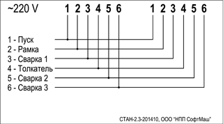
Models of the control units for the welding machine
| Name | Number of managed transformers | 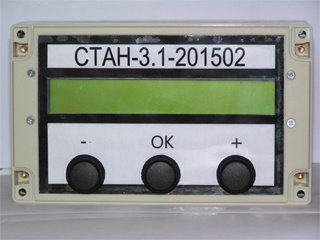 |
 |
|
|---|---|---|---|---|
| STAN-3.1 | 1 | |||
| STAN-3.2 | 2 | |||
| STAN-3.3 | 3 |
Possible development of control devices for machine tools of any specialization in technical requirements.
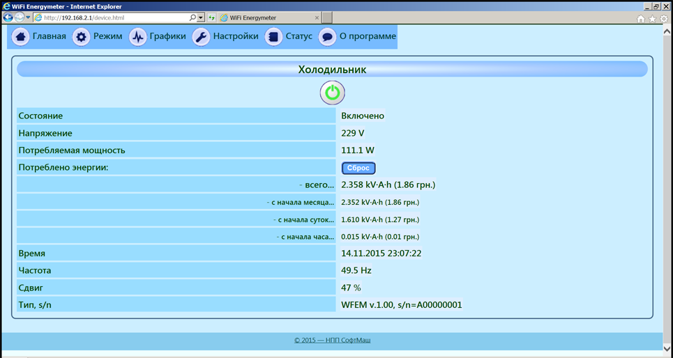
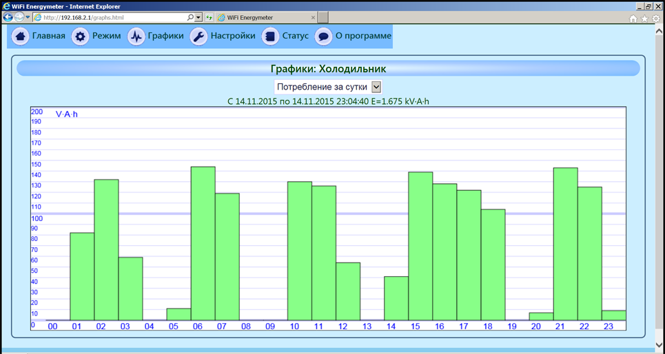
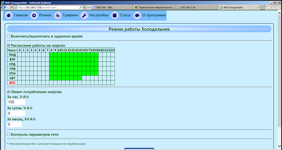
WiFi EnergyMeter

WiFi Energymeter - WiFi socket with the functions of electricity meter and a variety of programmable operating modes
"Accounting and control"
The device will accurately account for energy consumption and set a more efficient mode of its use
This is not just WiFi socket and electricity meter and the control functions and the optimization of consumption.Features of the device:
- high precision metering of electricity consumption
- no need to install any applications and works with all kinds of WiFi clients (laptops, tablets, mobile phones, desktop computers)
- the device is fully autonomous and does not require internet access or WiFi network
- internal real time clock
- the ability to integrate with other systems through an open API
- flexible choice of operating modes: off-line, in the home network to the Internet
- the ability to choose the level of protection: the password to WiFi, login password, the ability to hide the access point, or turn it off (included for setting only)
- the ability to send data to a site on the Internet to store and view, and in the establishment of a separate authorization to perform control commands from the site
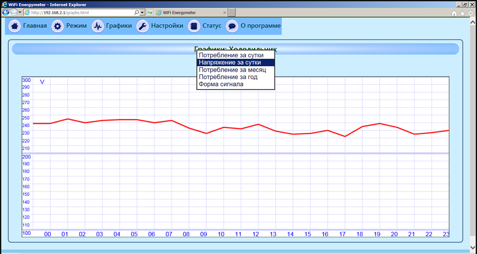
- the ability to set power mode: switch-off time, job schedules work on days of the week, setting a limit energy consumption per hour / day / month, the protection of minimum and maximum voltage and a combination of these modes
- voltage shutoff function to protect equipment in excess or undervoltage
User guide -
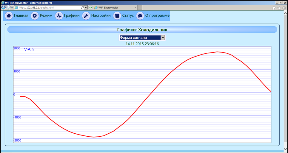
For high-precision measurements of power and energy consumed in the device uses WiFi EnergyMeter ADE7756 chip, developed by Analog Devices.